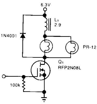
A Simple Power Consumption Limiter Circuit Diagram solenoid driver uses incandescent lamp filaments as on-indicators to limit power consumption. High magnetic reluctance (opposition to flux) in the coil of an armature-driven device, such as a solenoid or relay, calls for a surge of activation current, followed hy a lower de level to remain on, since surge to on-current ratio is typically 5:1. The cold filament allows a surge of coil-activation current to pass through; as the filament heats up, it throttles the current to a more reasonable hold value. The solenoid driver circuit offers these features: 5-V logic swings turn the power-MOSFET switch, Q1, fully on and off. 1vo low-cost flashlight lamps, in parallel, handle the peak current. Because their de current is only 50% of peak and because they operate at 60% of their rated voltage, the lamps have an operating life of 12,000 hours. Further, the lamp filaments` positive temperature coefficients raise each filament`s resistance. This rise in resistance eliminates current-hogging problems and provides short -circuit protection. The steady-state on-current is 700 mA, vs. 1700 mA without the lamps. A 4.6-V min supply rating allows battery operation.
Power Consumption Limiter Circuit Diagram

0 komentar:
Posting Komentar