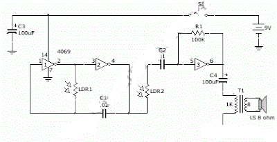
Normally, Theremin works by detecting hand proximity using capacitive coupling method. A Theremin circuit shown in the schematic diagram below use different method to control the pitch. The oscillator of this tone generator, both the volume and frequency are controlled using LDRs, a light sensitive electronic component, so we can call this circuit an optical Theremin. Look at the following schematic diagram.
Simple Optical Theremin Circuit Diagram
LDR1 control the frequency of this Theremin, while LDR2 control the volume level. We can place the LDR in two boxes where we can use our hand to control the aperture of the box, allowing smooth control of light amount that expose the LDR.
This light is expected to come from ambient light, entering the box through the hand controlled aperture. This optical Theremin assume a stable ambient light to produce smooth control. The output will be heard on a small loudspeaker, but will be in very low volume. You can just amplify this output with a standard audio power amplifier to get better loudness.

0 komentar:
Posting Komentar