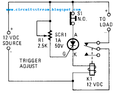
This is a Over voltage Protection Circuit Diagram. A silicon-controlled rectifier is installed in parallel with the 12-V line and connected to a normally-closed 12-V relay, K1. The SCR's gate circuit is used to sample the applied voltage. As long as the applied voltage stays below a given value, SCR1 remains off and Kl's contacts remain closed, thereby supplying power to the load.
When the source voltage rises above 12 V, sufficient current is applied to the gate of SCR1 to trigger it into conduction. The trigger point of SCR1 is dependent on the setting of R1. Once SCR1 is triggered (activating the relay), K1's contacts open, halting current flow to the load.
Over voltage Protection Circuit Diagram

0 komentar:
Posting Komentar