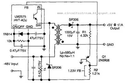
This is the Simple but Best Telecom Converter Circuit Diagram.The circuit supplies 1 A at +5 V from the -48-V supply commonly used in telephone equipment. The National Semiconductor LM2575 is a simple switching regulator.
Best Telecom Converter Circuit Diagram
Written By MR HARI on Rabu, 11 September 2013 | 12.52
Related Articles
If you enjoyed this article just click here, or subscribe to receive more great content just like it.
Label:
Converter

0 komentar:
Posting Komentar